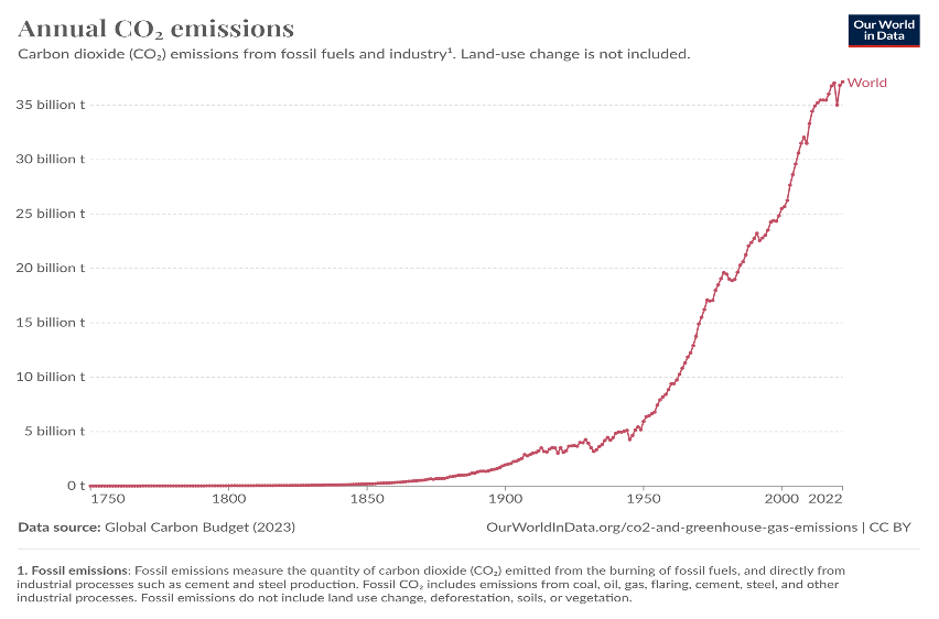
Unabated emission of greenhouse gases post industrialization is resulting in global warming. Energy related CO2 emissions drastically increased from about 5 Gt/year in 1950s to over 37 Gt in 2023. As a result, the concentration of CO2 in atmosphere increased from about 310ppm in 1950 to about 410 in 2020s. This has resulted in global warming by about 1oC. Further increase in global warming can have serious implications to the world resulting in calamities.
1. Introduction
Climate change is a major driver for countries around the world to adopt measures to drastically reduce the greenhouse gas (GHG) emissions. Most of the countries set their targets to achieve net zero by 2050. The effort is to contain global warming to withing 2°C, preferably to within 1.5 °C.
The CO2 emissions allowance to contain global warming within 1.5°C and 2°C derived from the carbon budget concept are estimated by the Intergovernmental Panel on Climate Change (IPCC) and others. Based on these estimates, the maximum amount of CO2 that can be emitted while still having a chance to limit global warming to these temperature thresholds is very small compared to the total annual emissions and necessitates immediate action. The data is given in the subsequent sections.
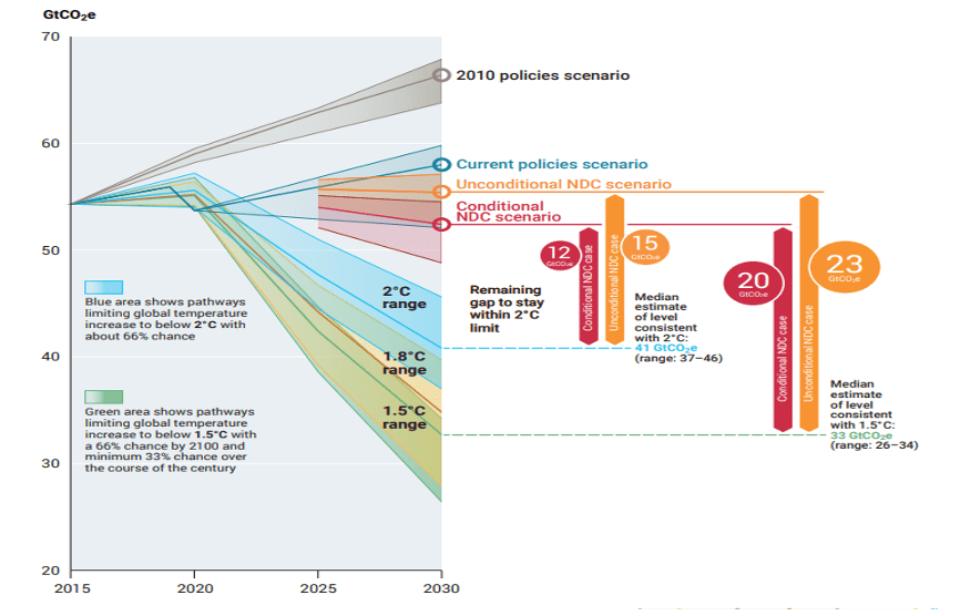
UNEP – ‘Emissions Gap Report 2022: The Closing Window’, reported GHG emissions under different scenarios and emission gap in 2030 to contain global warming within 1.5oC and 2oC. The data shown in Fig. 3 reveal that the remain gap to stay within 2oC ranges from 12-15 Gt and for 1.5oC it is 20-23 Gt by 2030 under different scenarios. This means to contain the global warming even with 2oC about 12-15 Gt emissions per year are to be reduced by 2030.

1.1 Carbon budget for 1.5°C Target
To limit global warming to 1.5°C above pre-industrial levels, the remaining carbon budget from the beginning of 2020 is estimated to be about 400-500 gigatonnes of CO2 (Gt CO2). This budget corresponds to roughly a decade of current global emissions if no significant reductions are made. This is really scary and quick actions are urgently required to limit the GHG emissions by all the concerned.
1.2 Carbon Budget for 2°C Target
To limit global warming to 2°C, the remaining carbon budget is estimated to be about 1,000-1,200 Gt CO2 from the beginning of 2020. This provides a slightly longer timeframe (about two decades) for reducing emissions but still requires substantial and immediate action to avoid surpassing this limit.
1.3 GHG emissions by top emitting countries
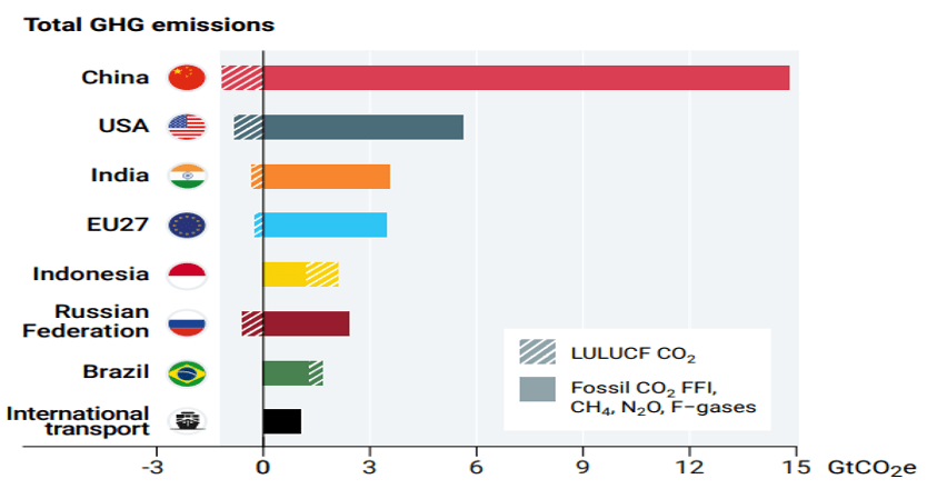
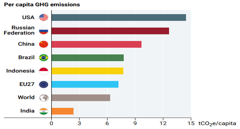
The top 7 emitting countries and International transport (Fig. 4) account for 55% of global emissions. These top countries are China, USA, India, EU27, Indonesia, Russian Federation and Brazil in that order. G20 member countries are responsible for 7%% emissions. However, when we look at per capita emissions (Fig.5) the picture is quite different. India’s per capita emissions are far less than many major countries and less than 50% of world average.
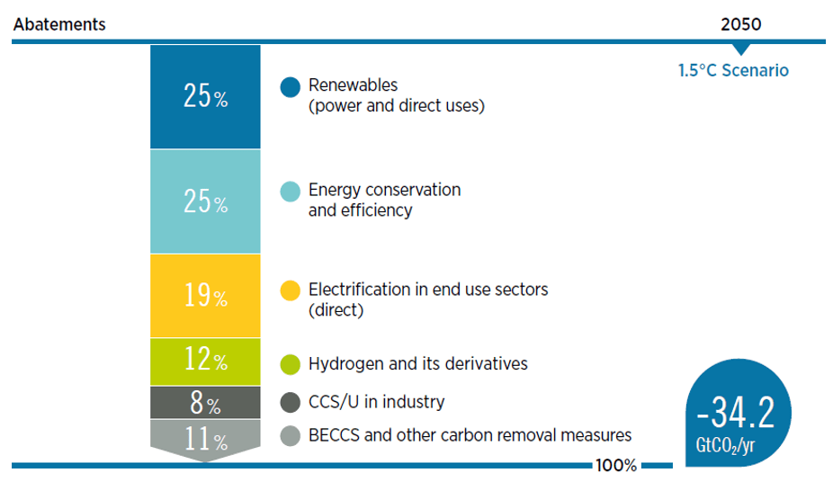
To limit the CO2 emissions, many countries set 2050 as target to achieve net zero targets. There are several pathways to achieve net zero. As per International Renewable Energy Agency, the important pathways include renewables, energy conservation and efficiency, electrification in end use sectors, hydrogen and its derivatives and CCUS – carbon capture, utilization and storage (Fig. 6). About 20% emission reductions are expected to be resulted from carbon capture, utilization and conversions. Hence, CCUS is one of the most important pathways to achieve net zero.
1.4 Existing planned commercial CCUS facilities
1.4.1 World Scenario
As per IEA report there are around 45 commercial carbon capture facilities in operation globally, with a total annual capture capacity of more than 50 Mt CO2. In 2023 about ten large-scale (capture capacity over 100 000 tCO2/year, and over 1 000 tCO2/yr for DAC applications) capture facilities entered operation in 2023.
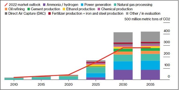
As per Bloomberg NEF report, over 140 Mt/yr of new capture capacity has been announced since 2022. With an expected growth of 18% compound the carbon capture capacity is expected to reach 420 million tons per annum by 2035 which is about 1.1% of current global annual emissions from fuel combustion and industrial processes. Ammonia/ hydrogen production and power generation are sectors are expected to account for 33% of the total capture capacity by 2035.
The world’s first commercial scale CO2-to-methanol plant started production in 2022 at Shunli (majority-owned by the Henan Shuncheng Group) in Anyang, Henan Province, China with 110,00 tons methanol per year capacity. The process is based on the Emissions-to-Liquids (ETL) technology developed by Carbon Recycling International (CRI), first demonstrated in Iceland. The new facility can capture 160,000 tons of CO2 emissions a year, which is equivalent to taking more than 60,000 cars off the road. The captured CO2 (from existing lime production emissions) is reacted with H2 (recovered from coke-oven gas) in CRI’s proprietary ETL reactor system. CRI’s second project in China was announced last year and is expected to come online in the second half of 2023.
1.4.2 Indian Scenario
India is the second-largest manufacturer of cement and steel, the third-largest consumer of energy, and the fourth-largest petroleum refinery. In its updated NDCs (Nationally determined contributions), India in 2022, reiterated a target to reduce its CO2 emissions intensity of GDP by 45% in 2030, compared to 2005 levels. The country aims for 50% of the total electricity capacity to be based on non-fossil fuel sources in 2030 (the previous target was 40%) from 36% in 2021. India is also considering implementing a carbon market. Indian Government set 2070 as target for achieving net-zero.
Many large Indian industries such as RIL, ONGC, NTPC and other set their targets to achieve net zero by 2047 as against National target of 2070.
Tata Steel has set up a 5 ton/day CO2 capture plant at its Jamshedpur works. Tuticorin Alkali Chemicals and Fertilizers has set up a 60,000 tons/yr CO2 capture plant. NTPC has setup a 20tons/day CO2 capture facility in their Vindyachal power plant (by Carbon Clean a UK based company). Plans to convert the captured CO2 to green methanol using green H2 produced by electrolysis using PEM based electrolyzers. IOCL is establishing a CCU project at its Koyali Refinery. ONGC and Equinor have signed an MoU to collaborate on CO2-enhanced oil recovery. NALCO is in the process of setting up CCUS facilities to capture and store carbon dioxide emissions from its operations. BHEL is exploring the implementation of CCUS technologies, focusing on capturing emissions from its power plants and industrial units. Dalmia Cement has committed to becoming carbon negative by 2040 and is working on several CCUS initiatives to capture CO2 emissions from its cement manufacturing processes. Many more CO2 capture plants are expected in the coming years to meet the reduced emission targets.
2. Carbon capture methods
There are several methods of carbon capture, each with its unique processes and applications. Details are given below.
2.1 Post-Combustion Capture
In this method, CO2 is captured from the flue gases produced after the combustion of fossil fuels. Amine-based solvents are commonly used to absorb CO2 from flue gases. The CO2-rich solvent is then heated to release CO2, which is subsequently compressed and stored. Suitable for retrofitting existing power plants and industrial facilities. This method can be used in the existing plants without major modifications. One of the disadvantages of this methods is that the existing technologies are energy-intensive due to the need to regenerate solvents.
2.2 Pre-Combustion Capture
In this method, CO2 is removed from fossil fuels before combustion. It involves gasification or reforming of fuels (e.g., coal, natural gas) to produce a synthesis gas (syngas) followed by water gas shift reaction. The resultant gas mainly consists of hydrogen and CO2. The CO2 is separated, and the hydrogen is used as a clean fuel. This method is most suited for Integrated Gasification Combined Cycle (IGCC) plants. This method produces a clean hydrogen fuel and concentrated CO2 stream. However, pre-combustion capture process is complex technology and involve high capital costs.
2.3 Oxy-Combustion Capture
In this method, pure oxygen is used for fuel combustion instead of air as a result it produces flue gas that is mostly CO2 and water vapor. After cooling, water vapor condenses, leaving high purity CO2 stream suitable for sequestration and conversion to value added fuels and products. This type of process is suitable for new power plants designed specifically for oxy-combustion. However, the process require air separation to produce oxygen, which is both capital and energy-intensive.
2.4 Chemical Looping
Chemical looping process uses metal oxides as oxygen carriers to transfer oxygen from the combustion air to the fuel. This technology involves two reactors: an air reactor where metal oxides are oxidized and a fuel reactor where they are reduced by reacting with fuel, producing CO2 and water vapor. This technology is still under developmental / demonstration stage having potential for high efficiency. The process inherently separates CO2 without energy-intensive gas separation.
Pre-combustion and oxy-combustion processes due to high capital costs and high energy requirements these are not popular as of now. Post-combustion carbon capture seems to be more acceptable process.
Each carbon capture method has its own advantages and disadvantages. These are summarised in Table 1 below.
| Method | Main Technology | Applications | Advantages | Disadvantages |
| Post-Combustion | Sorption using amine solvents or solid adsorbents | Retrofitting existing plants | Can be added to existing infrastructure | Energy-intensive regeneration |
| Pre-Combustion | Gasification, reforming | IGCC plants | Produces clean hydrogen, concentrated CO2 | High capital costs, complex technology, energy intensive |
| Oxy-Combustion | Pure oxygen combustion | New power plants | High-purity CO2 stream | Energy-intensive air separation and capital intensive |
| Chemical Looping | Metal oxides as oxygen carriers | Experimental, high efficiency potential | Inherent CO2 separation | Still in developmental stage. |
In addition to the above, the other process attracting lot of attention is Direct Air Capture (DAC) of CO2. Atmospheric air contains about 410 ppm CO2 and capturing carbon from such low concentration is expensive. However, DAC has certain advantages. For more details the reader may refer to my blog on DAC.
3. Post-combustion carbon capture
In this article, our focus is on post-combustion carbon capture. For post-combustion capture, there are three major processes as explained below –
3.1 Absorption process
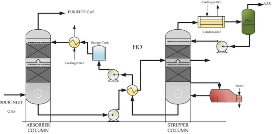
In an absorption process flue gas containing CO2 is contacted with an amine solution in a packed column. About 25-30 % amine in aqueous solution pumped to the top of the column and flue gas is passed from the bottom of the column in a countercurrent flow. Gas when gets in contact with amine solution, CO2 present in the gas selectively reacts with amine leave CO2 free gas at the top. The rich amine collected at the bottom is sent to regenerator where it is heated to 120 – 130°C to release pure CO2. The lean amine solution is then recycled to the column. A typical amine absorption process is shown in Fig. 8. The commonly used amines are MEA (monoethanolamine), AMP (2-Amino-2-methylpropanol), MDEA (methyldiethanolamine) and PIPA (Piperazine).
Primary alkanolamines such as MEA and DGA (diglycolamine) provide high chemical reactivity, kinetics, medium absorption capacity and selectivity. MEA is the most well-known, easily available at low cost. Even though MEA based absorption technology is suitable for acid gas removal, for CO2 capture from flue gases, there are several drawbacks such as high energy required for regeneration, low absorption capacity oxidative and thermal degradation and corrosion problem. To overcome the above drawbacks, efforts are being made to develop better sorbents which can be regenerated at low temperature, preferably below 100oC and with higher absorption capacity. DGA has properties similar to MEA except that it possesses low vapor pressure allowing its use at higher concentration between 40-60% in aqueous solution.
Secondary alkanolamines and tertiary amines are also studied for CO2 capture. Secondary alkanolamines such as diethanolamine (DEA) and siisopropanolamine (DIPA) having a hydrogen atom bonded to nitrogen shows intermediate properties compare to primary amines. DEA is more resistant to degradation and has better corrosion resistance.On the othe hand DIPA require lower temperature for regeneration. Tertiary amines such as triethanolamine (TEA) and methydiethanolamine (MDEA) possess lower absorption capacity and absorption kinetics, but higher stability.
3.1.1 Novel Sorbent System
Existing absorption process is extensively used in the industry for acid gas removal and natural gas processing and CO2 capture is highly mature technology. However, there are several challenges in the technology, important being the low CO2 absorption capacity, requirement of high temperature for regeneration, corrosion, and stability of amine.
To overcome some these challenges, there are efforts to develop novel sorbents including mixed amines, phase change sorbents, ionic liquids and deep eutectic solvents.
Mixed Amines: Some of the mixed amines such as MEA+AMP showed better performance to carbon capture (Source: Pao-Chi Chen, et al., ‘Selection of Mixed Amines in the CO2 Capture Process’, J Carbon Res., C 2021, 7, 25).
Phase Change (PC) Sorbents: Certain solvents undergo phase change from liquid solid or aqueous soluble liquid to insoluble liquid on absorption of CO2. In such cases, only the reacted amine in the solid form or insoluble liquid form needs to be regenerated resulting in reduction of energy required for the process.
Deep Eutectic Solvents (DES): Deep eutectic solvents (DESs) are a class of solvents that are being studied for their potential to capture carbon dioxide (CO2). DESs are made by combining hydrogen bond donors (HBDs) with hydrogen bond acceptors (HBAs) in a specific ratio, which creates a eutectic mixture with a lower melting point than either of its components. DESs can capture CO2 through physical dissolution at high CO2 partial pressures, or by forming carbamates when their HBD units react with CO2. DESs are environment friendly and hence attracted attention as green solvents for CO2 capture, especially for industrial applications.
Some examples of DESs CO2 capture are listed below:
- Monoethanolamine hydrochloride—ethylenediamine – Has a high gravimetric uptake of 33.7 wt% and good initial kinetics, with a 25.2 wt% uptake within 2.5 minutes.
- Choline chloride-based (ChCl) DESs – Can absorb CO2 at high CO2 partial pressures, with phenol-ChCl DES (nphenol/nChCl = 2:1) reaching a solubility of up to 0.18 mol CO2/mol DES at 40 °C and 503 kPa .
Ionic Liquids: Ionic liquids are promising due to their low volatility, high thermal stability, and tunable properties. They can potentially offer higher CO2 solubility and selectivity compared to traditional solvents. The solubility of CO2 in ionic liquids is governed primarily by the anion, less so by the cation. The hexafluorophosphate (PF6-) and tetrafluoroborate (BF4–) anions have been shown to be especially amenable to CO2 capture.
3.1.2 Process Intensification
There are also efforts to improve the absorption process through process intensification. The important process intensification routes are (1) use of rotating packed bed (RPB) and (2) use hollo fiber membrane contactors (HFMC) and (3) micro channel absorbers (MCA).
The packed column generally provides low surface to volume ratios, in the range of 700-800 m2/m3 of the column for gas liquid interaction limiting the mass transfer coefficient. On the other hand, when RPB, HFMC or Microscale absorbers are used, the surface to volume ratio can be increased by over 10 time – 8000-10,000 m2/m3 resulting in enhanced mass transfer. This would result in higher sorption capacity for a given sorbent, lower temperature required for regeneration and also lower foot print of the plant. Hence, the above process can result in lower capital cost and energy requirement.
Rotating Packed Beds (RPBs): RPBs use centrifugal force to improve gas-liquid contact, leading to higher mass transfer rates and reduced equipment size. This can significantly enhance the absorption process compared to conventional packed columns.
Hollo Fiber Membrane Contractor (HFMC): HFMCs are an alternative membrane package type that significantly enhances the mass transfer area versus the direct gas-liquid process (absorption). In addition, the HFMCs provide better separation performance based on the driving force, selectivity, and absorption efficiency than the conventional membrane separation process.
Micro Channel Absorbers (MCA): Utilizing microchannel reactors can improve mass transfer and reaction kinetics due to their high surface-to-volume ratios. This leads to more efficient CO2 absorption in a compact system.
3.2 Adsorption process:
There are mainly two type of adsorption processes for CO2 capture, viz., (a) Pressure Swing Adsorption (PSA) process and (b) Temperature Swing Adsorption (TSA) process.
3.2.1 Pressure Swing Adsorption (PSA) Process
PSA operates by cycling the pressure of the gas mixture through adsorbent beds. Generally the process uses at least 2 beds (Fig. 9) Flue gas at near atmospheric temperature is passed through the 1st adsorbent beds in which CO2 is selectively adsorbed. Once the bed is saturated with CO2, the feed gas is switched to the 2nd bed. The 1st bed then undergoes regeneration by reducing the bed pressure. When the feed is available at near atmospheric pressure, regeneration is done by applying vacuum. Type of adsorption involved in a PSA process is physisorption. Common adsorbents used in the process include zeolites, activated carbon, and metal-organic frameworks (MOFs). Typically the process is performed at ambient to moderately low temperatures (often between 20°C to 50°C). The major advantage of the PSA process is the use of short cycle times resulting in efficient use of adsorbents leading to high feed throughputs.

3.2.2 Temperature Swing Adsorption (TSA) Process
TSA process operates by cycling the temperature of the adsorbent beds. In TSA generally two beds are used. Flue gas at near atmospheric temperature is passed through the 1st adsorbent beds in which CO2 is selectively adsorbed. Once the bed is saturated with CO2, the feed gas is switched to the 2nd bed. The 1st bed is then heated to higher temperature for regeneration. In TSA process flue gas at high temperature, typically at 90-120oC can be directly used without heating. Type of adsorption involved in the process is chemisorption. Materials like amine-functionalized silica, metal oxides, and some MOFs are effective at higher temperatures. Typical regeneration temperatures can be in the range of 120-200oC.
One of the major advantages orTSA process is that feed can used at higher temperatures directly without cooling. provide effective regeneration of adsorbents at higher temperatures. However, energy is require for heating and cooling the beds during regeneration. As heating and cooling takes time, TSA generally operates on longer cycles times compared to PSA resulting is inefficient use of adsorbents which limits the throughput.
The choice between PSA and TSA for CO2 capture depends on the specific operational conditions and available resources. PSA is generally preferred for low to moderate temperature applications due to its energy efficiency and rapid cycling capabilities. TSA is advantageous in high-temperature applications where waste heat can be utilized. Each method has its trade-offs, and the selection should be based on a comprehensive assessment of the process requirements, energy availability, and economic considerations.
Adsorption processes both PSA and TSA are extensively used in the industry for gas separation and purification. Adsorption based processes are also measured technologies.
The focus of research with respect to adsorption process is the development of novel adsorbent materials with high adsorption capacity, selectivity for CO2. Two type of adsorption materials are being developed based on (1) physisorption and (2) chemisorption.
3.3 Membrane process
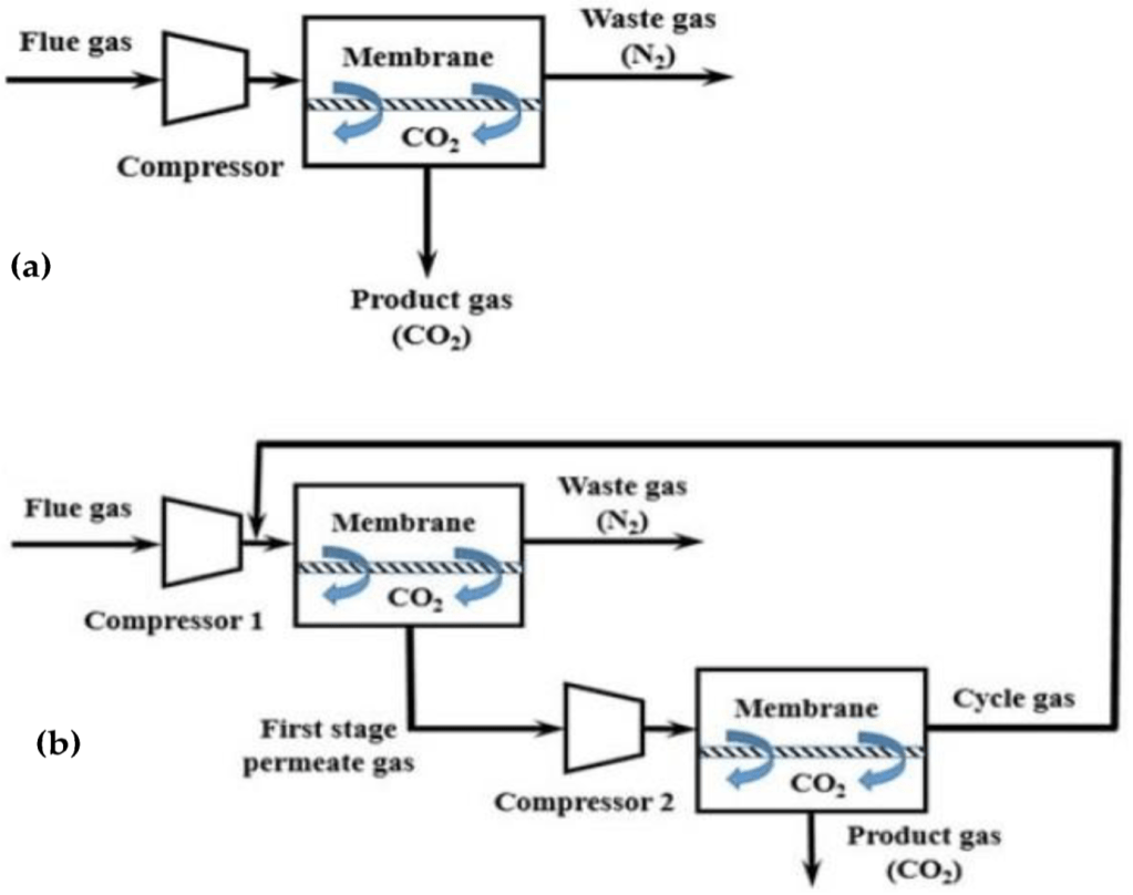
In a membrane process, a membrane acts as a filter that allows specific molecules to permeate (e.g., CO2) but prevents other molecules from entering the membrane (e.g., CH4 and H2O) due to characteristics such as gas–membrane chemical interactions or the kinetic diameter.
For gas separation dense membranes with no permanent porosity are used. In such membranes, the most widely adopted mechanism/model for mass transport is the solution-diffusion model. In dense membrane, gas transport occurs in three steps: (1) dissolution or sorption of a gas into the membrane at the high-pressure material side, (2) diffusion of the sorbed gas through the membrane, and (3) desorption of the gas from the membrane at the low-pressure material side. The chemical potential difference between the high-pressure and low-pressure contacting phases controls the driving force, which is created through gas compression or vacuum.
The permeability is equal to the product of gas solubility and diffusivity in the membrane. Selectivity expresses the ability of a membrane to separate two gases. In membrane technologies, selectivity and permeability are the most important parameters for efficient gas separation and determine the process economics. The energy required for the process (operating cost) is controlled by selectivity, and the membrane area required for a given plant capacity (capital cost) is controlled by permeability.
Typical membrane configurations for separating CO2 include hollow fiber (HF), flat-sheet (FS) and spiral-wound (SW) membranes. Hollow fiber membranes, which contain hundreds or thousands of hollow fibers packed into bundles, are the most studied membrane configuration due to their high surface area per unit volume, which promotes gas transfer. However, they present drawbacks, such as fiber fouling and significant pressure drops. On the contrary, flat-sheet membranes, which are usually stacked on top of each other, present lower pressure drops and enhanced mass transfer because they employ specially designed feed spacers. In addition, they can be easily fabricated and physically or chemically cleaned. Spiral-wound membranes actually consist of flat-sheet membranes that are rolled around a collection tube.
Among various membrane materials, polymeric materials present inherent advantages in terms of cost, variety and ease of processing. Polymeric materials studied for CO2 capture include – polyacetylene, polyaniline, polyamides, polyimides, polyetherimides, polycarbonates, poly(phenylene oxides), poly(ethylene oxides), polysulfones and cellulose acetate.
3.3.1 Commercial polymers for CO2 capture
Three commercial membrane modules have been successfully demonstrated for post-combustion capturing of CO2 from flue gases. These are PolarisTM, PolyActiveTM and PRISMTM modules.
PolarisTM, was developed by Membrane Technology and Research (MTR) (USA). PolarisTM Gen 1, possessing a CO2 permeance of 1000 GPU and a CO2/N2 selectivity of 50, has been tested commercially for CO2 capture. PolarisTM spiral-wound membranes exhibited prolonged membrane performance (>111,000 h) and achieved >90% CO2 capture on a bench scale (0.05 MWe or 1 tons of CO2/day). A larger pilot-scale system (1 MWe or 20 tons of CO2/day) also presented stable operation (>6 months), achieving 90% CO2 capture. Polaris Gen 2, with twice the CO2 permeance but similar CO2/N2 selectivity, showed higher CO2 separation performance (60–70%), compared to Gen 1, and also exhibited stable performance for >40 h when it was tested on a laboratory scale.
Helmholtz-Zentrum Geesthacht (Geesthacht, Germany) developed PolyActiveTM module showed high CO2 permeance of 3068 m3 (STP)/m2/h/bar (1136 GPU), and high CO2/N2 selectivity (60), with a CO2 recovery of 42.7% and a CO2 purity of 68.2%. PRISM™ modules are developed by Air Products (Allentown, PA, USA).
4. Challenges in CO2 Capture
High cost: The most significant barrier to the deployment of CCUS technologies is the high equipment and energy cost needed for the capture and compression phases. Capturing the CO2 decreases a plant’s efficiency and increases water use.
As per IEA report 2021 cost estimate for CO2 capture from:
- Power plant flue gases – USD 60-120/ton CO2 (low CO2 concentration)
- Hydrogen (SMR) plant off gases – USD 50-80 ton CO2 (high CO2 concentration).
This challenge offers a huge opportunity to develop better technologies with lower costs.
Storage challenges: Captured CO2 is typically stored underground, usually in former oil and gas reservoirs which have been proven to have held their resources in place for millions of years. The capacity of these underground geological formations to store CO2 is limited, and not all sites may be suitable for long-term storage. Hence, there is a need to identify and assess potential storage sites, which can be expensive.
Infrastructure challenges: Suitable storage sites can be remote, so captured CO2 may need to be transported across large distances, requiring a network of pipelines. The cost of building and maintaining these pipelines can be high. These cost issues may also apply to the storage infrastructure itself, as even existing geological sites are likely to need to be adapted for the safe storage of CO2 and monitored to ensure there is no leakage.
Impact of CO2 on material: CO2 can have significant adverse effects on materials, including corrosion, degradation, scaling, and embrittlement. For example, when CO2 reacts with water, it can form carbonic acid. When moisture contaminates pipelines transporting CO2, it can lead to corrosion in metal components and pipes, particularly those made from carbon steel or copper alloys. This, in turn, can lead to leakage, which is often difficult to detect, and can be dangerous and expensive to repair.
5. Work being carried out at CSIR-IICT
At CSIR-IICT Hyderabad, the author along with his colleagues are actively work in on carbon capture by the following processes:
- Aprocess using phase change amines and deep eutectic solvents (DES) as sorbents.
- Adsorption process using novel adsorbents such as amine functionalised MOFs. porous silica, porous organic polymers (POPs).
- Intensified membrane process using hallo fiber membrane contactors.
- Sorption enhanced methane steam reforming (SESMR) with inherent CO2 capture and
- Chemical looping hydrogen production with CO2 capture.
Conclusion
Carbon capture, utilization, and storage (CCUS) technologies are pivotal in the global effort to mitigate climate change by reducing greenhouse gas emissions. The urgency to act is underscored by the limited carbon budgets available to maintain global warming within 1.5°C and 2°C thresholds. With the current global emissions rates, these budgets highlight the necessity for immediate and substantial reductions in CO2 emissions.
Globally, the deployment of commercial CCUS facilities is expanding, with significant capacity increases expected in the coming decades. The technologies vary from post-combustion capture to innovative methods using phase change amines and deep eutectic solvents. Notably, the world’s first commercial CO2-to-methanol plant in China exemplifies the advancements in carbon conversion technologies, demonstrating the feasibility and benefits of such initiatives.
In India, the commitment to reducing CO2 emissions intensity and achieving net-zero targets by 2070 is driving the adoption of CCUS technologies across various industries. Major companies are investing in carbon capture plants and exploring carbon conversion methods, showcasing the potential for large-scale implementation in emerging economies.
The challenges of CCUS, including high costs, infrastructure needs, and material impacts, are significant but not insurmountable. Continued research and development, such as the work being conducted at CSIR-IICT Hyderabad, are essential to advancing these technologies and making them more cost-effective and efficient.
Overall, CCUS represents a critical component of the multifaceted approach required to address climate change. As the technology evolves and more projects come online, its role in reducing global emissions and supporting sustainable development will become increasingly important.

Leave a comment